


Everything You Need to Know About Inductor Symbol
 8056
8056Global electronic component supplier ERSAELECTRONICS: Rich inventory for one-stop shopping. Inquire easily, and receive fast, customized solutions and quotes.
Basic Concepts of Inductor
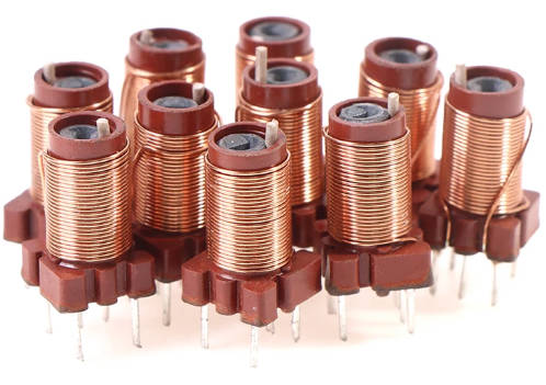
An element that transforms electrical energy into magnetic energy and stores it is called an inductor. An inductor has a single winding but otherwise resembles a transformer in structure. A certain amount of inductance included in inductors merely prevents the shift in current. When the circuit is open, the inductor will attempt to keep the current from flowing through it if it is not in a state where it is carrying current, and it will attempt to keep the current constant if it is carrying current.
.jpg)
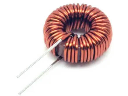
Figure 1: Inductor
Key Parameters of Inductors
| Parameter | Description | Typical Values/Units |
| Inductance (L) | The ability of the inductor to store energy in its magnetic field. | nH (nanohenries), µH (microhenries),mH (millihenries), H (henries) |
| Rated Current | The maximum current the inductor can handle without overheating or saturation. | mA (milliamperes), A (amperes) |
| DC Resistance (DCR) | The resistance of the inductor to direct current affects energy losses. | mΩ (milliohms), Ω (ohms) |
| Self-Resonant Frequency (SRF) | The frequency at which the inductor’s impedance becomes purely resistive, above which it behaves like a capacitor. | kHz (kilohertz), MHz (megahertz) |
| Saturation Current | The current at which the core material of the inductor becomes saturated causes a drop in inductance. | mA (milliamperes), A (amperes) |
| Core Material | The material used in the core of the inductor affects its inductance and performance. | Air, Iron, Ferrite, Powdered Iron |
| Shielding | Indicates whether the inductor is shielded to reduce electromagnetic interference (EMI). | Shielded, Unshielded |
| Tolerance | The precision of the inductance value represents the possible variation from the specified value. | ±1%, ±2%, ±5%, ±10%, ±20% |
| Temperature Coefficient | The change in inductance with temperature indicates thermal stability. | ppm/°C (parts per million per degree Celsius) |
| Rated Voltage | The maximum voltage the inductor can withstand without breakdown. | V (volts) |
| Peak Current | The maximum instantaneous current the inductor can handle. | mA (milliamperes), A (amperes) |
| Core Loss | The energy loss in the core material is due to hysteresis and eddy currents, usually given at specific frequencies and flux densities. | W (watts), mW (milliwatts) |
| Insulation Resistance | The resistance between the inductor winding and the core or other components ensures isolation. | MΩ (megohms) |
| Thermal Resistance | The ability of the inductor to dissipate heat is usually specified as a temperature rise per unit of power dissipation. |
°C/W (degrees Celsius per watt) |
| Storage Temperature Range | The temperature range over which the inductor can be safely stored without performance degradation. | °C (degrees Celsius) |
Inductor Model Naming Rules
| Parameter | Description | Example |
| Series/Family | Indicates the manufacturer series of the inductor. | LQH, IHLP, MLC |
| Size/Dimensions | Specifies the physical size of the inductor, often in metric or imperial units. | 0603, 1210 |
| Inductance Value | Specifies the inductance value, usually in microhenries (µH), millihenries (mH), or nanohenries (nH). | 100 (for 10 µH), 1R0 (for 1.0 µH) |
| Tolerance | Indicates the tolerance level of the inductance value. | J (±5%), K (±10%), M (±20%) |
| Rated Current | Specifies the maximum current the inductor can handle without overheating. | 1R0 (for 1.0 A), 470 (for 470 mA) |
| DC Resistance (DCR) | The resistance to direct current affects the overall efficiency. | R10 (for 0.1 Ω), R47 (for 0.47 Ω) |
| Core Material | Indicates the material used for the core of the inductor. | F (Ferrite), I (Iron), A (Air) |
| Shielding | Indicates whether the inductor is shielded to prevent electromagnetic interference (EMI). | S (Shielded), U (Unshielded) |
| Packaging | Describes the type of packaging for the inductor. | T (Tape & Reel), B (Bulk) |
| Additional Features | Any additional characteristics or features. | H (High Current), L (Low Profile) |
| Manufacturer Code | Unique code assigned by the manufacturer for specific identification. | 01, 02 |
How to Use the Inductor?
A closed loop's inductance is the ability to withstand fluctuations in current by creating an electric potential as the loop's current flows through it. This inductance is inherent to the closed loop and is referred to as self-inductance. This inductance is known as mutual inductance if it is assumed that an electromotive force in one closed loop results from a change in current due to inductive action.
Self-induction is the application of the aforementioned self-induction phenomena. One characteristic of a circuit (typically a coil) is self-inductance. Because of the magnetic effect that the current induces, the voltage in the circuit will fluctuate as the current fluctuates. In other words, self-inductance is an inductance that exists in a single coil and is applicable to a single circuit. This effect is utilized for chokes or single coils.
The formula for Inductance:
The induced voltage VL is equal to the number of coil turns times the change in magnetic flux per unit of time. According to the electromagnetic induction theory of mutual inductance, the magnetic field that connects the two circuits acts to modify the voltage across one circuit when the current in the other circuit changes. Transformers utilize this phenomenon.

Regardless of self-inductance or mutual inductance, only alternating current can function, and the only thing that can cause induced current to occur is the shifting magnetic field that the changing current creates. Direct current has an inductance that is comparable to an extended wire.
Difference between Common Mode Inductors and Differential Mode Inductors
| Parameter | Common Mode Inductors | Differential Mode Inductors |
| Purpose | Designed to suppress common mode noise (interference affecting both lines equally) | Designed to suppress differential mode noise (interference between two lines) |
| Noise Suppression | Effective at reducing noise that appears identically on both lines of a pair | Effective at reducing noise that appears between two lines |
| Construction | Typically consists of two windings on a single core with the same number of turns | Often a single winding or two separate windings are not coupled in the same way as common mode inductors |
| Core Material | Usually ferrite cores for high-frequency noise suppression | Can be ferrite or other magnetic materials depending on the application |
| Operation | Opposing magnetic fields in the core when common mode current flows, canceling the interference | Single magnetic field for differential mode current, suppressing noise between lines |
| Applications | Common in power supplies, data lines, and audio equipment to eliminate EMI and RFI | Used in power supplies, differential signaling circuits, and audio equipment to ensure signal integrity |
| Impedance Characteristics | High impedance to common mode signals, low impedance to differential mode signals | High impedance to differential mode signals, may have a negligible effect on common mode signals |
| Typical Configuration | Two windings are wound in such a way that their magnetic fields oppose each other for common mode currents | A single winding or two separate windings that do not interact in the same manner as common mode inductors |
| Symbol in Schematics | Often represented with a coil symbol and dots indicating phase on both windings | Represented with standard inductor symbols, without the phase indication dots |
| Typical Usage Frequency | Effective across a wide range of frequencies, particularly high frequencies (kHz to GHz range) | Effective at specific frequency ranges depending on the design, often used in lower frequency ranges (Hz to MHz) |
| Advantages | High efficiency in suppressing common mode noise without affecting differential signals | Effective in maintaining the integrity of differential signals by reducing noise between lines |
| Disadvantages | Not effective for differential mode noise | Not effective for common mode noise suppression |
| Examples of Use | USB cables, Ethernet cables, audio signal lines, power supply input filters | Power supply output filters, differential signal lines such as balanced audio cables, and twisted pair Ethernet lines |
What is an Inductor Symbol?
An inductor component is represented graphically in electrical schematics by an inductor symbol, which is a standardized representation. It’s used to show where an inductor is located in an electrical circuit and usually looks like a sequence of coils or loops. In order to ensure correct assembly and troubleshooting, this symbol aids engineers and technicians in understanding the circuit's design and operation. The inductor symbol may differ slightly throughout standards like ANSI, IEC, IEEE, and JIS, but they all share the same basic function.
Types of Inductors and Their Inductor Symbols
| Image | Type | Inductor Symbol | Description |
 |
Variable Inductor |
Figure 2: Variable Inductor Symbol |
The inductance of this kind of inductor varies. In radios, for example, its inductance can be adjusted while the circuit is operating. |
 |
Iron Core Inductor |
Figure 3: Iron Core Inductor Symbol |
This kind of inductor has iron (a ferromagnet) as its core material. The high magnetic permeability of the iron core causes the inductor's inductance to increase. |
 |
Ferrite Core Inductor |
Figure 4: Ferrite Core Inductor Symbol |
The ferrite core of these inductors is what their name implies. To lower the losses inside the core, the ferrite material has low electrical conductivity and high magnetic permeability. High-frequency applications employ them. |
 |
Variable Ferrite Core Inductor |
Figure 5: Variable Ferrite Core Inductor Symbol |
It is a particular kind of ferrite core with varying inductance. By adjusting the core inside the coil, these inductors' inductance can be changed. |
 |
Shielded Inductor |
Figure 6: Shielded Inductor Symbol |
The magnetic field within an inductor core of this kind is intended to be contained. Leakage flux that can affect other components nearby is not well understood. These are utilized in small-form printed circuit boards (PCBs) where space management is crucial. |
 |
Bifilar Inductor |
Figure 7: Bifilar Inductor Symbol |
The bifilar inductor coil consists of two conductors that are parallel to one another. To neutralize the mutually created magnetic field, the winding conductors might be oriented antiparallel, or in the opposite direction of the current flow. To double the coil's magnetic field, they can be placed in parallel. |
 |
Variometer |
Figure 8: Variometer Symbol |
The variometer is a type of variable inductor that moves two coils that are connected in series with one another to continuously adjust the inductance. |
Different Standards for Inductor Symbols
| Standard | Organization | Description |
| ANSI | American National Standards Institute | A standard coil symbol with arcs, representing an inductor. Typically, a coiled wire. |
| IEC | International Electrotechnical Commission | A series of loops, typically drawn as a single line with several arcs. |
| IEEE | Institute of Electrical and Electronics Engineers | Similar to the ANSI standard, with a series of arcs representing the coiled wire. |
| JIS | Japanese Industrial Standards | Often similar to IEC, but sometimes includes specific annotations unique to Japanese standards. |
How to Draw an Inductor Symbol?
To ensure that the inductor symbol in circuit diagrams is universally recognized, it is necessary to draw it according to conventional rules. Here's how to draw a simple inductor symbol and its modifications step-by-step.
| Types of Inductor Symbols | Steps | Inductor Symbols |
| Basic Inductor Symbol | 1. Draw a Straight Line: The base of the symbol will be a straight line drawn either horizontally or vertically. |
__/\/\/\__ Figure 9: basic inductor symbol |
| 2. Add Coils/Loops: Sketch a sequence of connected semi-circular arcs or loops along the line. Three to four loops should work just fine. | ||
| 3. Maintain Consistency: To keep the shape neat and identifiable, make sure the loops are spaced equally and of the same size. | ||
| Iron-Core Inductor Symbol | 1. Draw the Basic Inductor Symbol: To draw a basic inductor symbol, follow these steps. |
__/\/\/\__ Figure 10: iron core inductor symbol |
| 2. Include the central representation. To depict the iron core, draw a rectangle or two parallel lines across the middle of the loops. | ||
| Ferrite-Core Inductor Symbol | 1. Draw the Basic Inductor Symbol: To draw a basic inductor symbol, follow these steps. |
__/\/\/\__ Figure 11: ferrite-core inductor symbol |
| 2. Include Core Material Annotation: Label or annotate the symbol in the circuit design to show that it is a ferrite-core inductor, even though it may not alter visibly. | ||
| Toroidal Inductor Symbol | 1. Draw the Basic Inductor Symbol: To draw a basic inductor symbol, follow these steps. |
__/\/\/\__ Figure 12: toroidal inductor symbol |
| 2. Annotate for Toroidal Shape: Since the visual depiction stays the same, add a comment or label identifying it as a toroidal inductor. | ||
| Variable Inductor Symbol | 1. Draw the Basic Inductor Symbol: To draw a basic inductor symbol, follow these steps. |
__/\/\/\__ Figure 13: variable inductor symbol |
| 2. Add an Arrow: To show variability, draw a diagonal arrow through the inductor's loops. | ||
| Choke Inductor Symbol | 1. Draw the Basic Inductor Symbol: To draw a basic inductor symbol, follow these steps. |
__/\/\/\__ Figure 14: choke inductor symbol |
| 2. Add Choke Lines: To show that something is a choke, draw brief, parallel lines across the loops. |
Inductor Schematic Symbol
The coil nature of an inductor is shown by its circuit symbol. The inductor or transformer's magnetic or air core can be determined using one of several formats.
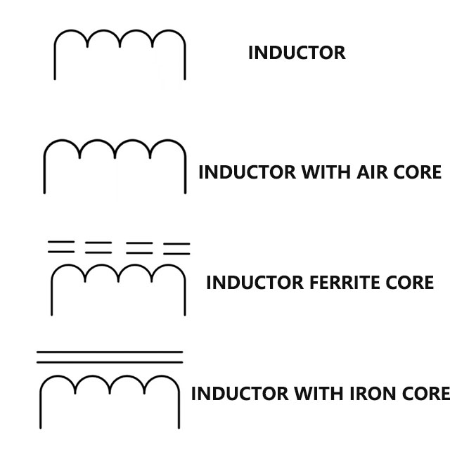
Figure 15: inductor circuit symbols
Transformers have a wide range of uses, even though basic inductors are commonly utilized in many circuits.

Figure 16: transformer circuit symbols
The advantage of ferrite and iron cores is that they improve the coupling between the input and output inductors in a transformer as well as the amount of inductance. They do cause losses. Lower levels of inductance are required for radio frequency (RF) applications, which is where air-cored inductors and transformers come in handy.
What is the Symbol used for an Inductor in the Schematic Diagram?
An inductor is shown as a succession of semi-circular arcs or loops along a straight horizontal line in a schematic diagram; this represents the inductor's coiled wire. To help convey specific characteristics and functionalities of the inductor within the circuit, this basic symbol can be slightly modified to indicate different types of inductors. For example, an arrow can be added for a variable inductor, parallel lines for an iron-core inductor, or annotation for a ferrite-core or toroidal inductor.
Electronic circuit diagrams will always be interpreted consistently thanks to the standardization of these symbols by numerous international organizations, including IEEE, ANSI, and IEC. Engineers and technicians can help with the design, analysis, and troubleshooting of electrical circuits by precisely identifying the type of inductor used, its core material, and any unique properties by understanding these symbols.
How to Read and Interpret Inductor Symbols in Schematics
1. Determine the Symbol:
- In the diagram, look for the sequence of semi-circular arcs or loops.
- Identify any extra labels or comments that identify the specific kind of inductor.
2. Examine the label:
- Locate the label (L1, L2, etc.) attached to the inductor.
- Cross-reference the inductor's specs using the label with the documentation for the circuit or parts list.
3. Recognize the requirements:
- Please consult the inductance value (in Henries, H) that is supplied in the documentation.
- Verify further details such as the core material, tolerance, and current rating.
4. Examine the Situation:
- Look at the circuit's inductor connections.
- Considering its location and the components around it, ascertain its function (e.g., filtering, energy storage, coupling).
 FAQ
FAQ